Tuesday, 14 April 2015

Light Emitting Elements And Their Types

INTRODUCTION

The use and application of light cannot be overemphasized. Our natural source of light being an electromagnetic radiation that reaches us from the sun. Without that radiation, no life would remain on this planet.
The ultraviolet ray reaching us from the sun is trapped by the green plants. They make use of it to manufacture their own food which we in turn consume. In the stone ages, men lit fire to enhance their vision at night. As time swiftly went by, man began to amaze the body of knowledge as new discoveries were made.
Man soon thought of how to artificially generate light. Inventions were made and it’s still improving. From light emitting elements that consumed a lot of energy, dissipating most of it in form of heat while a minute fraction of it is converted to light to a modern light emitting devices that consumes less energy, less heat production and with more efficiency. Thomas Edison did a very good job and credit goes to him for inventing the fluorescent Bob.
How is light energy generated from electricity? Before we talk about that, let’s check out some few things first so as to have a better understanding.Light Emitting Elements And Their Types

HEAT FROM ELECTRICITY

Electricity produces heat. The heat produced (in case) of the flow of electric current through a conductor containing impurities that opposes the flow of current. The free movement of electrons between atoms in a lattice along a conducting wire constitutes heat.
During movement, electrons collide with each other and with the atoms, hence heat is produced in the process. Resistance of a conducting wire is also a factor that constitutes to the heat a conducting wire produces. Let the Heat produced during conduction is designated by H.
It is proportional to the resistance R of the conductor and proportional to the time (t) for the current to flow through the conductor and also proportional to the square of the current. Hence if the constant k of proportionality is 1,
H = I2Rt.

it is also known as Joule’s Law.

HEATING EFFECT OF ELECTRIC CURRENT

When high current is passed through a conductor, the resultant is an immense heat production. The collision of electrons occurs frequently and causes an increase in the internal energy of the atoms thereby making the electrons to vibrate because of the heat energy acquired. At high temperature, some wires glow.
All the electrical energy is converted to heat. At low current and temperature, the conducting wire will not glow due to the lack of sufficient energy needed to excite the electrons to jump from one energy level to the other which will lead to the production of light in the process.

LIGHT FROM ELECTRICITY

From our discussion above, we can tell that electricity can be converted to light energy. When we turn on our home switch, light turns on, the electric bobs converts electrical energy to light energy.
The light comes from the heating effect of electricity. Devices that converts electricity into light was discovered long ago and since then have been improved. The early devices had very low efficiency in that it consumed a lot of energy.
The bad side of the early devices consumed a lot of heat and converts only the minute fraction of the energy it consumes into light. Today there are electric bobs that have high efficiency compared to the early ones. They consume less energy and convert most of the energy to light.
Below are some electrical elements that convert electricity into light with their mode of operation.

FILAMENT LAMP:

a filament lamp glows white hot. At high temperature, part of the electrical energy is converted into light energy while the rest is converted to heat energy. In a filament lamp, tungsten filament is enclosed in a glass. Earlier lamps used carbon as a filament which also has high melting point.
The original tungsten lamp had a vacuum inside the envelope to prevent the oxidation of the tungsten at high temperature. Modern lamps are prevented from evaporation by filling it with argon. The quartz-iodine lamp produces light of high intensity.
The envelope is made of quartz which can stand high temperature without melting. The tungsten filament lamp converts only 7% of the energy it receives into light and the rest will be converted to heat.
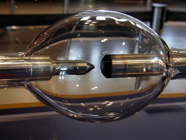
FILAMENT LAMP
Filament Lamp (Bulb)

DISCHARGE LAMP:

discharge lamps are with sodium vapor, neon gas, mercury vapor etc. Sodium and mercury vapor gives yellow light and are used in street lighting. Electrical discharge is passed through the gases.
When the gases absorb energy, they become excited. The atoms emit light in the red region when they become excited. The lamps that indicates when a main socket is switched on is generally a small neon lamp. Neon discharge tubes can have different shapes and are also used in advertising display.
Discharge Lamp
Discharge Lamp

FLUORESCENT LAMP:

Fluorescent lamps are widely used in offices, factories, shops etc because of its efficiency. Its efficiency is about three times the efficiency of the filament lamp. Its heat production is low. You can easily tell that by holding the lamp after minutes of turning on of the lamp. It contains mercury vapor and argon.
During discharge, mercury vapor emits light of considerable wavelength including the ultraviolet radiation. The inner surface of the tube is coated with fluorescent material to absorb the ultraviolet (UV) radiation and emits the absorbed energy in the form of visible light.
FLUORESCENT LAMP
FLUORESCENT LAMP

LIGHT EMITTING DIODE (LED):

Diodes are semiconductors. Some of them emit light when their atoms become excited due to the electrical energy they receive. They are small in size, some even less than 1mm in diameter. They are often used as indicator lamps. They have long life span and is not easily broken. The illuminated figures in pocket calculators, digital watches and digital clocks are usually made from LED.
Each digit consists of seven bar-shaped diodes arranged in a pattern similar to figure eight. Groups of diode are lit to form any figure, letters of the alphabet. Its advantage is that they lit up in a very short (they don’t require warming) and goes dark easily when they are cut off from power supply.
LIGHT EMITTING DIODE (LED)
To cut down your electricity bill, avoid using lamps that consumes too much energy. Don’t think by turning off the other appliances and leaving the lamps on, electricity bills won’t pile up. Use lamps that consume less energy like the fluorescent lamps and if necessary that you use the filament lamps, turn it off after use.

CPDWD GENERAL SPECIFICATION FOR ELECTRICAL WORKS

Thursday, 9 April 2015

Complete overview of lightning arresters

Complete overview of lightning arresters 

Complete overview of lighting arresters
Top

Lightning and Voltage Surge

Rod arrester
Rod arrester
Lightning can create voltage surges in several of the following ways. Lightning can score a direct hit on your house. It can strike the overhead power line which enters your house, or a main power line that is blocks away from your home. Lightning can strike branch circuitry wiring in the walls of your house.
Lightning can strike an object near your home such as a tree or the ground itself and cause a surge. Voltage surgescan be created by cloud to cloud lightning near your home. A highly charged cloud which passes over your home can also induce a voltage surge.
Voltage surges can also be caused by standard on and off switching activities of large electric motors or pieces of equipment. These surges can be created by a neighbor, or by a business or manufacturing facility some distance from your house. These surges are insidious and for the most part are silent.
They can occur with little or no warning.
Top

Methodology to Suppress Lighting and Voltage Surge:

When a voltage surge is created, it wants to equalize itself and it wants to do it as quickly as possible. These things seem to have very little patience. The surges will do whatever it takes to equalize or neutralize themselves, even if it means short circuiting all of your electronic equipment.
The method of providing maximum protection for equipment is quite simple. Create a pathway for the voltage surge (electricity) to get to and into the ground outside your house as quickly as possible.
This is not, in most cases, a difficult task.
The first step is simple. Create an excellent grounding system for your household electrical system. The vast majority of homes do not have an excellent grounding system. Many homes have a single grounding rod and /or a metallic underground water pipe which are part of the electrical grounding system. In most cases, this is inadequate. The reason is somewhat easy to explain. Imagine putting a two inch fire hose into your kitchen sink and opening the nozzle to the full on position. I doubt that the drain in your sink could handle all of the water. Your grounding system would react in the same way to a massive voltage surge. Just as the water jumps out of the sink, the electricity jumps from the grounding system and looks for places to go. Frequently it looks for the microchips in your electronic devices. They are an easy target. They offer a path of least resistance.
Voltage surges want to be directed to the grounding system, and when they do, they want to get into the ground around your house in a hurry. You can achieve this by driving numerous grounding rods into virgin soil around your house. These rods should be UL approved and connected by a continuous heavy solid copper wire which is welded to each grounding rod. This solid copper wire begins on the grounding bar inside of your electrical panel and terminates at the last grounding rod. Avoid using clamps if at all possible. Over time, the connection at the clamp can corrode or become loose creating tremendous resistance. This will act as a roadblock to the electricity trying to get into the ground around your home.
The grounding rods should be at least ten feet apart from one another. They should be located in soil which readily accepts electricity. Moist clay soils are very desirable. Rocky, sandy, or soils with gravel generally have high resistance factors. Electricity has a tough time dissipating into them. Resistance readings should be in the range of 10 to 30 ohms. The lower the better.
The second step in household surge protection is to install a lightning arrester inside of your electric service panel. These devices can be extremely effective in intercepting large voltage surges which travel in the electric power lines. These devices capture the voltage surges and ‘bleed’ them off to the grounding wire which we just spoke of. If for some reason you do not have a large enough grounding wire, or enough ground rods, the arrester cannot do its job. It must be able to send the surge quickly to the ground outside of your house. These arresters range in price from $50.00 to $175.00. Almost every manufacturer of circuit breakers makes one to fit inside their panel. They can be installed by a homeowner who is experienced in dealing with high voltage panels. If you do not have this capability, have an experienced electrician install it for you.
The final step in the protection plan is to install ‘point of use’ surge suppression devices. Often you will see these called ‘transient voltage surge suppressors’. These are your last line of defense. They are capable of only stopping the leftover voltage surge which got past the grounding system and the lightning arrester. They cannot protect your electronic devices by themselves. They must be used in conjunction with the grounding system and the lightning arresters. Do not be lulled into a false sense of security if you merely use one of these devices!
The ‘point of use’ surge suppression devices are available in various levels of quality.Some are much better than others. What sets them apart are several things. Generally speaking, you look to see how fast their response time is. This is often referred to as clamping speed. Also, look to see how high of a voltage surge they will suppress. Make sure that the device has a 500 volt maximum UL rated suppression level. Check to see if it has an indicator, either visual or audio, which lets you know if it is not working. The better units offer both, in case you install the device out of sight. Check to see if it offers a variety of modes with respect to protection. For example, does the device offer protection for surges which occur between the ‘hot’ and neutral, between ‘hot’ and ground, as well as between neutral and ground. There is a difference! Check to see if it monitors the normal sine waves of regular household current. Surges can cause irregularities in these wave patterns. Good transient surge suppression devices ‘devour’ these voltage spikes. Finally, check the joule rating. Attempt to locate a device which has a joule rating of 140 or higher. Electrical supply houses often are the best place to look for these high quality devices.
Some devices can also protect your phone equipment at the same time. This is very important for those individuals who have computer modems. Massive voltage surges can come across phone lines as well. These surges can enter your computer through the telephone line! Don’t forget to protect this line as well. Also, be sure the telephone ground wire is tied to the upgraded electrical grounding system.

Complete overview of lightning arresters (part 2)

Complete overview of lighting arresters
Top
Continued from article Complete overview of lightning arresters (part 1)

What is a surge arrester?

Surge arresters are devices that help prevent damage to apparatus due to high voltages. The arrester provides a low-impedance path to ground for the current from a lightning strike or transient voltage and then restores to a normal operating conditions.
A surge arrester may be compared to a relief valve on a boiler or hot water heater. It will release high pressure until a normal operating condition is reached. When the pressure is returned to normal, the safety valve is ready for the next operation.
When a high voltage (greater than the normal line voltage) exists on the line, the arrester immediately furnishes a path to ground and thus limits and drains off the excess voltage. The arrester must provide this relief and then prevent any further flow of current to ground. The arrester has two functions; it must provide a point in the circuit at which an over-voltage pulse can pass to ground and second, to prevent any follow-up current from flowing to ground.
Top

Causes of over voltages

  • Internal causes
  • External causes

Internal causes

Switching surge

The overvoltages produced on the power system due to switching are known as switching surge.

Insulation failure

The most common case of insulation failure in a power system is the grounding of conductors (i.e. insulation failure between line and earth) which may cause overvoltage in the system.

Arcing ground

The phenomenon of intermittent arc taking place in line to ground fault of a 3phase system with consequent production of transients is known as arcing ground.

Resonance

It occurs in an electrical system when inductive reactance of the circuit becomes equal to capacitive reactance. under resonance , the impedance of the circuit is equal to resistance of the circuit and the p.f is unity.
Top

Types of lightning strokes

  1. Direct stroke
  2. Indirect stroke

(1) Direct stroke

In direct stroke, the lightning discharge is directly from the cloud to the subject equipment. From the line, the current path may be over the insulator down the pole to the ground.

(2) Indirect stroke

Indirect stroke results from the electro statically induced charges on the conductors due to the presence of charge clouds.
Top

Harmful effects of lightning

The traveling waves produced due to lightning will shatter the insulators. If the traveling waves hit the windings of a transformer or generator it may cause considerable damage.

Protection against lightning

Different types of protective devices are:
  1. Earthing screen
  2. Overhead ground wires
  3. Lightning arresters

(1) The Earthing screen

The power station & sub-station can be protected against direct lightning strokes by providing earthing screens. On occurrence of direct stroke on the station ,screen provides a low resistance path by which lightning surges are conducted to ground.
Limitations: It does not provide protection against the traveling waves which may reach the equipments in the station.

(2) Overhead ground wires

It is the most effective way of providing protection to transmission lines against direct lightning strokes. It provides damping effect on any disturbance traveling along the lines as it acts as a short-circuited secondary.
Limitations:
  • It requires additional cost.
  • There is a possibility of its breaking and falling across the line conductors, thereby causing a short-circuit fault.

(3) Lightning Arresters

It is a protective device which conducts the high voltage surge on the power system to ground. The earthing screen and ground wires fail to provide protection against traveling waves. The lightning arrester provides protection against surges.
Top

AC Power Surge Arrester

Type 1 Surge Protectors

Type 1 surge protectors are designed to be installed where a direct lightning strike risk is high, especially when the building is equipped with external lightning protection system (LPS or lightning rod).
In this situation IEC 61643-11 standards require the Class I test to be applied to surge protectors : this test is characterized by the injection of 10/350 μs impulse current in order to simulate the direct lightning strike consequence. Therefore these Type 1 surge protectors must be especially powerful to conduct this high energy impulse current.

Type 2 surge protectors

Type 2 surge protectors are designed to be installed at the beginning of the installation, in the main switchboard, or close to sensitive terminals, on installations without LPS (lightning rods). These protectors are tested following the Class II test from IEC61643-11 based on 8/20 μs impulse current injection.

Type 3 surge protectors

In case of very sensitive or remote equipment, secondary stage of surge protectors is required : these low energy SPDs could be Type 2 or Type 3. Type 3 SPDs are tested with a combination waveform (1,2/50 μs – 8/20 μs) following Class III test.

Types of Lightning Arrestors according to Class

1. Station Class

  • Station class arrestors are typically used in electrical power stations or substations and other high voltage structures and areas.
  • These arrestors protect against both lightning and over-voltages, when the electrical device has more current in the system than it is designed to handle.
  • These arrestors are designed to protect equipment above the 20 mVA range.

2. Intermediate Class

  • Like station class arrestors, intermediate class arrestors protect against surges from lightning and over-voltages, but are designed to be used in medium voltage equipment areas, such as electrical utility stations, substations, transformers or other substation equipment.
  • These arrestors are designed for use on equipment in the range of 1 to 20 mVA.

3. Distribution Class

  • Distribution class arrestors are most commonly found on transformers, both dry-type and liquid-filled.
  • These arrestors are found on equipment rated at 1000 kVA or less.
  • These arrestors are sometimes found on exposed lines that have direct connections to rotating machines.

4. Secondary Class

  • Secondary class lightning arrestors are designed to protect most homes and businesses from lightning strikes, and are required by most electrical codes, according to, Inc., an electrical power protection company.
  • These arrestors cause high voltage overages to ground, though they do not short all the over voltage from a surge. Secondary class arrestors offer the least amount of protection to electrical systems, and typically do not protect solid state technology, or anything that has a microprocessor.
Top

Choosing the right AC Power Surge Arrester

AC power surge protectors is designed to cover all possible configurations in low voltage installations. They are available in many versions, which differ in:
  • Type or test class (1 , 2 or 3)
  • Operating voltage (Uc)
  • AC network configuration (Single/3-Phase)
  • Discharge currents (Iimp, Imax, In)
  • Protection level (Up)
  • Protection technology (varistors, gas tube-varistor, filter)
  • Features (redundancy, differential mode, plug-in, remote signaling…).
The surge protection selection must be done following the local electrical code requirements (i.e. minimum rating for In) and specific conditions (i.e. high lightning density).
Top

Working Principle of Lightning Arrester

The earthing screen and ground wires can well protect the electrical system against direct lightning strokes but they fail to provide protection against traveling waves, which may reach the terminal apparatus. The lightning arresters or surge diverts provide protection against such surges. A lightning arrester or a surge diverted is a protective device, which conducts the high voltage surges on the power system to the ground.
The earthing screen and ground wires can well protect the electrical system against direct lightning strokes but they fail to provide protection against traveling waves, which may reach the terminal apparatus. The lightning arresters or surge diverters provide protection against such surges. A lightning arrester or a surge diverted is a protective device, which conducts the high voltage surges on the power system to the ground.
Fig below shows the basic form of a surge diverter.
Basic form of a surge diverter

It consists of a spark gap in series with a non-linear resistor. One end of the diverter is connected to the terminal of the equipment to be protected and the other end is effectively grounded. The length of the gap is so set that normal voltage is not enough to cause an arc but a dangerously high voltage will break down the air insulation and form an arc. The property of the non-linear resistance is that its resistance increases as the voltage (or current) increases and vice-versa.
This is clear from the volt/amp characteristic of the resistor shown in Figure above.
The action of the lightning arrester or surge diverter is as under:
  1. Under normal operation, the lightning arrester is off the line i.e. it conducts no current to earth or the gap is non-conducting
  2. On the occurrence of over voltage, the air insulation across the gap breaks down and an arc is formed providing a low resistance path for the surge to the ground. In this way, the excess charge on the line due to the surge is harmlessly conducted through the arrester to the ground instead of being sent back over the line.
  3. It is worthwhile to mention the function of non-linear resistor in the operation of arrester. As the gap sparks over due to over voltage, the arc would be a short-circuit on the power system and may cause power-follow current in the arrester. Since the characteristic of the resistor is to offer low resistance to high voltage (or current), it gives the effect of short-circuit. After the surge is over, the resistor offers high resistance to make the gap non-conducting.
courtesy- Mr.Jignesh Parmar

Thursday, 2 April 2015

IAS ELECTRICAL ENGINEERING QUESTION PAPERS

EARTHING

What is Earthing

Introduction:

The main reason for doing earthing in electrical network is for the safety. When all metallic parts in electrical equipments are grounded then if the insulation inside the equipments fails there are no dangerous voltages present in the equipment case. If the live wire touches the grounded case then the circuit is effectively shorted and fuse will immediately blow. When the fuse is blown then the dangerous voltages are away.

Purpose of Earthing:

(1)  Safety for Human life/ Building/Equipments:

  • To save human life from danger of electrical shock or death by blowing a fuse i.e. To provide an alternative path for the fault current to flow so that it will not endanger the user
  • To protect buildings, machinery & appliances under fault conditions.
  • To ensure that all exposed conductive parts do not reach a dangerous potential.
  • To provide safe path to dissipate lightning and short circuit currents.
  • To provide stable platform for operation of sensitive  electronic equipments   i.e. To maintain the voltage at any part of an electrical system at a known value so as to prevent over current or excessive voltage on the appliances or equipment .

(2)  Over voltage protection:

  • Lightning, line surges or unintentional contact with higher voltage lines can cause dangerously high voltages to the electrical distribution system. Earthing provides an alternative path around the electrical system to minimize damages in the System.

(3)  Voltage stabilization:

  • There are many sources of electricity. Every transformer can be considered a separate source. If there were not a common reference point for all these voltage sources it would be extremely difficult to calculate their relationships to each other. The earth is the most omnipresent conductive surface, and so it was adopted in the very beginnings of electrical distribution systems as a nearly universal standard for all electric systems.

Conventional methods of earthing:

(1)  Plate type Earthing:

  • Generally for plate type earthing normal Practice is to use
  • Cast iron plate of size 600 mm x600 mm x12 mm. OR
  • Galvanized iron plate of size 600 mm x600 mm x6 mm. OR
  • Copper plate of size 600 mm * 600 mm * 3.15 mm
  • Plate  burred at the depth of 8 feet in the vertical position and GI strip of size 50 mmx6 mm bolted with the plate is brought up to the ground level.
  • These types of earth pit are generally filled with alternate layer of charcoal & salt up to 4 feet from the bottom of the pit.

(2)  Pipe type Earthing:

  • For Pipe type earthing normal practice is to use
  • GI pipe [C-class] of 75 mm diameter, 10 feet long welded with 75 mm diameter GI flange having 6 numbers of holes for the connection of earth wires and inserted in ground by auger method.
  • These types of earth pit are generally filled with alternate layer of charcoal & salt or earth reactivation compound.

Method for Construction of Earthing Pit (Indian Electricity Board):

  • Excavation on earth for a normal earth Pit size is 1.5M X 1.5M X 3.0 M.
  • Use 500 mm X 500 mm X 10 mm GI Plate or Bigger Size for more Contact of Earth and reduce Earth Resistance.
  •  Make a mixture of Wood Coal Powder Salt & Sand all in equal part
  •  Wood Coal Powder use as good conductor of electricity, anti corrosive, rust proves for GI Plate for long life.
  • The purpose of coal and salt is to keep wet the soil permanently.
  • The salt percolates and coal absorbs water keeping the soil wet.
  • Care should always be taken by watering the earth pits in summer so that the pit soil will be wet.
  • Coal is made of carbon which is good conductor minimizing the earth resistant.
  • Salt use as electrolyte to form conductivity between GI Plate Coal and Earth with humidity.
  • Sand has used to form porosity to cycle water & humidity around the mixture.
  • Put GI Plate (EARTH PLATE) of size 500 mm X 500 mm X 10 mm in the mid of mixture.
  • Use Double GI Strip size 30 mm X 10 mm to connect GI Plate to System Earthling.
  •  It will be better to use GI Pipe of size 2.5″ diameter with a Flange on the top of GI Pipe to cover GI Strip from EARTH PLATE to Top Flange.
  • Cover Top of GI pipe with a T joint to avoid jamming of pipe with dust & mud and also use water time to time through this pipe to bottom of earth plate.
  • Maintain less than one Ohm Resistance from EARTH PIT conductor to a distance of 15 Meters around the EARTH PIT with another conductor dip on the Earth at least 500 mm deep.
  • Check Voltage between Earth Pit conductors to Neutral of Mains Supply 220V AC 50 Hz it should be less than 2.0 Volts.

Factors affecting on Earth resistivity:

(1)  Soil Resistivity:    

  • It is the resistance of soil to the passage of electric current. The earth resistance value (ohmic value) of an earth pit depends on soil resistivity. It is the resistance of the soil to the passage of electric current.
  • It varies from soil to soil. It depends on the physical composition of the soil, moisture, dissolved salts, grain size and distribution, seasonal variation, current magnitude etc.
  • In depends on the composition of soil, Moisture content, Dissolved salts, grain size and its distribution, seasonal variation, current magnitude.

(2)  Soil Condition:

  • Different soil conditions give different soil resistivity. Most of the soils are very poor conductors of electricity when they are completely dry. Soil resistivity is measured in ohm-meters or ohm-cm.
  • Soil plays a significant role in determining the performance of Electrode.
  • Soil with low resistivity is highly corrosive. If soil is dry then soil resistivity value will be very high.
  • If soil resistivity is high, earth resistance of electrode will also be high.

(3)  Moisture:  

  • Moisture has a great influence on resistivity value of soil. The resistivity of a soil can be determined by the quantity of water held by the soil and resistivity of the water itself. Conduction of electricity in soil is through water.
  • The resistance drops quickly to a more or less steady minimum value of about 15% moisture. And further increase of moisture level in soil will have little effect on soil resistivity. In many locations water table goes down in dry weather conditions. Therefore, it is essential to pour water in and around the earth pit to maintain moisture in dry weather conditions. Moisture significantly influences soil resistivity

(4)  Dissolved salts:

  • Pure water is poor conductor of electricity.
  • Resistivity of soil depends on resistivity of water which in turn depends on the amount and nature of salts dissolved in it.
  • Small quantity of salts in water reduces soil resistivity by 80%. common salt is most effective in improving conductivity of soil. But it corrodes metal and hence discouraged.

(5)  Climate Condition:

  • Increase or decrease of moisture content determines the increase or decrease of soil resistivity.
  • Thus in dry whether resistivity will be very high and in monsoon months the resistivity will be low.

 (6)  Physical Composition:

  • Different soil composition gives different average resistivity. Based on the type of soil, the resistivity of clay soil may be in the range of 4 – 150 ohm-meter, whereas for rocky or gravel soils, the same may be well above 1000 ohm-meter.

 (7)  Location of Earth Pit :

  • The location also contributes to resistivity to a great extent. In a sloping landscape, or in a land with made up of soil, or areas which are hilly, rocky or sandy, water runs off and in dry weather conditions water table goes down very fast. In such situation Back fill Compound will not be able to attract moisture, as the soil around the pit would be dry. The earth pits located in such areas must be watered at frequent intervals, particularly during dry weather conditions.
  • Though back fill compound retains moisture under normal conditions, it gives off moisture during dry weather to the dry soil around the electrode, and in the process loses moisture over a period of time. Therefore, choose a site that is naturally not well drained.

 (8)  Effect of grain size and its distribution:

  • Grain size, its distribution and closeness of packing are also contributory factors, since they control the manner in which the moisture is held in the soil.
  • Effect of seasonal variation on soil resistivity: Increase or decrease of moisture content in soil determines decrease or increase of soil resistivity. Thus in dry weather resistivity will be very high and during rainy season the resistivity will be low.

(9)  Effect of current magnitude:

  • Soil resistivity in the vicinity of ground electrode may be affected by current flowing from the electrode into the surrounding soil.
  • The thermal characteristics and the moisture content of the soil will determine if a current of a given magnitude and duration will cause significant drying and thus increase the effect of soil resistivity

(10) Area Available:

  • Single electrode rod or strip or plate will not achieve the desired resistance alone.
  •  If a number of electrodes could be installed and interconnected the desired resistance could be achieved. The distance between the electrodes must be equal to the driven depth to avoid overlapping of area of influence. Each electrode, therefore, must be outside the resistance area of the other.

(11)  Obstructions:

  • The soil may look good on the surface but there may be obstructions below a few feet like virgin rock. In that event resistivity will be affected. Obstructions like concrete structure near about the pits will affect resistivity. If the earth pits are close by, the resistance value will be high.

(12)    Current Magnitude:

  • A current of significant magnitude and duration will cause significant drying condition in soil and thus increase the soil resistivity.

Measurement of Earth Resistance by use of Earth Tester:

  • For measuring soil resistivity Earth Tester is used. It is also called the “MEGGER”.
  • It has a voltage source, a meter to measure Resistance in ohms, switches to change instrument range, Wires to connect terminal to Earth Electrode and Spikes.
  • It is measured by using Four Terminal Earth Tester Instrument. The terminals are connected by wires as in illustration.
  • P=Potential Spike and C=Current Spike. The distance between the spikes may be 1M, 2M, 5M, 10M, 35M, and 50M.
  • All spikes are equidistant and in straight line to maintain electrical continuity.  Take measurement in different directions.
  • Soil resistivity =2πLR.
  • R= Value of Earth resistance in ohm.
  • Distance between the spikes in cm.
  • π  =  3.14
  • P = Earth resistivity ohm-cm.
  • Earth resistance value is directly proportional to Soil resistivity value

Measurement of Earth Resistance (Three point method):

 
  • In this method earth tester terminal C1 & P1 are shorted to each other and connected to the earth electrode (pipe) under test.
  • Terminals P2 & C2 are connected to the two separate spikes driven in earth.  These two spikes are kept in same line at the distance of 25 meters and 50 meters due to which there will not be mutual interference in the field of individual spikes.
  • If we rotate generator handle with specific speed we get directly earth resistance on scale.
  • Spike length in the earth should not be more than 1/20th distance between two spikes.
  • Resistance must be verified by increasing or decreasing the distance between the tester electrode and the spikes by 5 meter. Normally, the length of wires should be 10 and 15 Meter or in proportion of 62% of ‘D’.
  • Suppose, the distance of Current Spike from Earth Electrode D = 60 ft, Then, distance of Potential Spike would be 62 % of D = 0.62D i.e.  0.62 x 60 ft = 37 ft.

Four Point Method:

  • In this method 4 spikes are driven in earth in same line at the equal distance.  Outer two spikes are connected to C1 & C2 terminals of earth tester.  Similarly inner two spikes are connected to P1 & P2 terminals.  Now if we rotate generator handle with specific speed, we get earth resistance value of that place.
  • In this method error due to polarization effect is eliminated and earth tester can be operated directly on A.C.

 GI Earthing Vs Copper Earthing:

  • As per IS 3043, the resistance of Plate electrode to earth (R) = (r/A) X under root(P/A).
  • Where r = Resistivity of Soil Ohm-meter.
  • A=Area of Earthing Plate m3.
  • The resistance of Pipe electrode to earth (R) = (100r/2πL) X loge (4L/d).
  • Where L= Length of Pipe/Rod in cm
  • d=Diameter of Pipe/Rod in cm.
  • The resistivity of the soil and the physical dimensions of the electrode play important role of resistance of Rod with earth.
  • The material resistivity is not considered important role in earth resistivity.
  • Any material of given dimensions would offer the same resistance to earth. Except the sizing and number of the earthing conductor or the protective conductor.

 Pipe Earthing Vs Plate Earthing:

  • Suppose Copper Plate having of size 1.2m x 1.2m x 3.15mm thick. soil resistivity of 100 ohm-m,
  • The resistance of Plate electrode to earth (R)=( r/A)X under root(π/A) = (100/2.88)X(3.14/2.88)=36.27 ohm
  • Now, consider a GI Pipe Electrode of 50 mm Diameter and 3 m Long. soil resistivity of 100 Ohm-m,
  • The resistance of Pipe electrode to earth (R) = (100r/2πL) X loge (4L/d) = (100X100/2X3.14X300) X loge (4X300/5) =29.09 Ohm.
  • From the above calculation the GI Pipe electrode offers a much lesser resistance than even a copper plate electrode.
  • As per IS 3043 Pipe, rod or strip has a much lower resistance than a plate of equal surface area.

 Length of Pipe Electrode and Earthing Pit:

  •  The resistance to earth of a pipe or plate electrode reduces rapidly within the first few feet from ground (mostly 2 to 3 meter) but after that soil resistivity is mostly uniform.
  • After about 4 meter depth, there is no appreciable change in resistance to earth of the electrode. Except a number of rods in parallel are to be preferred to a single long rod.

 Amount of Salt and Charcoal (more than 8Kg) :

  •  To reduce soil resistivity, it is necessary to dissolve in the moisture particle in the Soil.
  • Some substance like Salt/Charcoal is highly conductive in water solution but the additive substance would reduce the resistivity of the soil, only when it is dissolved in the moisture in the soil after that additional quantity does not serve the Purpose.
  • 5% moisture in Salt reduces earth resistivity rapidly and further increase in salt content will give a very little decrease in soil resistivity.
  • The salt content is expressed in percent by weight of the moisture content in the soil. Considering 1M3 of Soil, the moisture content at 10 percent will be about 144 kg. (10 percent of 1440 kg). The salt content shall be 5% of this (i.e.) 5% of 144kg, that is, about 7.2kg.

 Amount of  Water Purring:

  •  Moisture content is one of the controlling factors of earth resistivity.
  • Above 20 % of moisture content, the resistivity is very little affected. But below 20% the resistivity increases rapidly with the decrease in moisture content.
  • If the moisture content is already above 20% there is no point in adding quantity of water into the earth pit, except perhaps wasting an important and scarce national resource like water.

 Length Vs Diameter of Earth Electrode:

  • Apart from considerations of mechanical strength, there is little advantage to be gained from increasing the earth electrode diameter with the object in mind of increasing surface area in contact with the soil.
  • The usual practice is to select a diameter of earth electrode, which will have enough strength to enable it to be driven into the particular soil conditions without bending or splitting. Large diameter electrode may be more difficult to drive than smaller diameter electrode.
  • The depth to which an earth electrode is driven has much more influence on its electrical resistance characteristics than has its diameter.

Maximum allowable Earth resistance:

  • Major power station= 0.5 Ohm.
  • Major Sub-stations= 1.0 Ohm
  • Minor Sub-station = 2 Ohm
  • Neutral Bushing. =2 Ohm
  • Service connection = 4 Ohm
  • Medium Voltage Network =2 Ohm
  • L.T.Lightening Arrestor= 4 Ohm
  • L.T.Pole= 5 Ohm
  • H.T.Pole =10 Ohm
  • Tower =20-30 Ohm

 Treatments to for minimizing Earth resistance:

  • Remove Oxidation on joints and joints should be tightened.
  • Poured sufficient water in earth electrode.
  • Used bigger size of Earth Electrode.
  • Electrodes should be connected in parallel.
  • Earth pit of more depth & width- breadth should be made.